Dear Golem,
The Jointmaster audio solution line amplifier amplifies the signal from your mobile phone stereo jack (or the signal from your desktop computer soundcard speaker output stereo jack) to so-called TTL level 5 Volt. At the same time it delivers sufficient current to switch opto-coupler LEDS on and off.
These opto-coupler LEDS can be found in all step motor drivers. All step motor drivers have enable, direction and pulse signals driven by the opto-coupler LEDS. For this reason the Line Amplifier main function is to: “Control a step motor driver”
We made effort to design the Jointmaster line amplifier so that it can be created using through hole components. Thus there is no real need for a Printed Circuit Board. However, buying our Jointmaste kit B here can be a time-saver because:
- Less chance there is an error in the wiring. If you blow up your OPAMP lm358 due to wrong wiring then this will cost some time, money and frustration.
- Less soldering of wires between components.
- You get an order-list to buy the components at RS-Online. Thus you will have the correct components.
- You get free Jointmaster Android + Windows software.
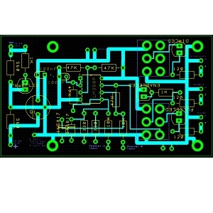
Soldering the audio solution line amplifier can be done in half an hour as shown here:
But you can also do it for less money using the Jointmaster audio 10 euro solution. The Jointmaster line amplifier technical manual is also included in the Jointmaster free version so that you can make a working application for free (but you will have to create your own software and decide what components to use). We will now give a pre-view of the Jointmaster line amplifier technical manual and also discusses where to connect stopswitches + safety switches if needed.
Inside the Jointmaster line amplifier technical manual manual you will find:
- The functionality explained
- The line amplifier interfaces explained
- The schema explained.
- Grounding/ EMC thoughts
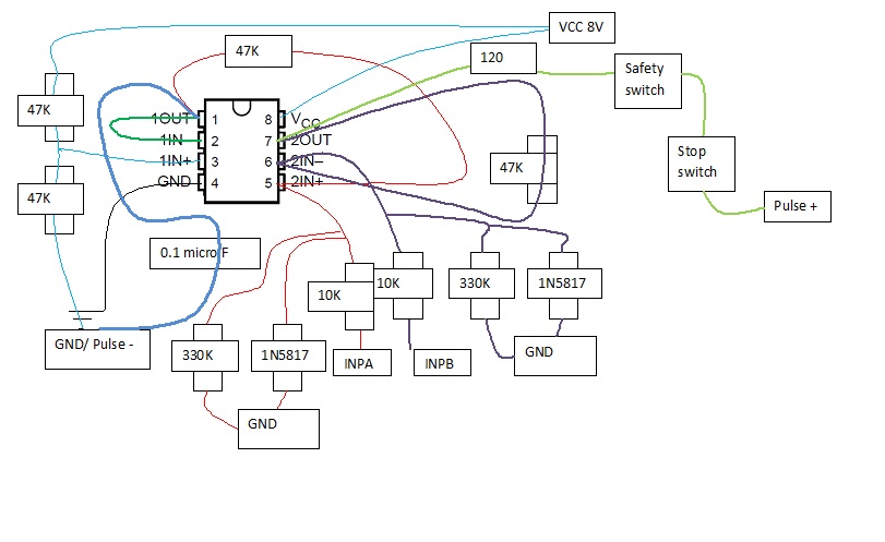
This picture below can be found in the manual where on the right one can see the Pulse signal. (We call this concept A). The pulse signal is connected to the step motor driver pulse. The sound from the phone is connected to INPA + INPB.

Now suppose we add safety switch and stop switches like this (We call this concept B):
Is concept B sufficiently safe ? It might be safe enough. Advantage is that the step motor stays enabled, cannot make new movements and will not inadvertantly move due to vibration. Also the stopswitches prevent your step motor from hitting the wall (If you use heavier step motors than we advertise, you need stop switches because your machine might break when it hits the wall). Disadvantage of concept B is that you add components that:
- might fail. For example dust in the switch leading to dust explosion 😉
- need maintenance
- add cost
- add resistance to the line amplifier circuit because all switches are in series to the Pulse signal.
An alternative concept C (no drawing available, you will have to design this yourself because so far we work without the safety switch) is to have the safety switch make the enable signal high. Yes, you read correct because when the enable signal is high, power is removed from the step motor. This is safer as the concepts A and B because when power is removed you can rotate the step motor spindle by hand and thus remove your hand from clamping jigs when you inadvertantly put your hands inside a step motor operated machine.
But think about this. You could also add a removable cover over all moving parts so that you can never put your fingers there (do not under estimate the pushing force of the small Jointmaster step motor in the Jointmaster box joint jig, around 200 Newton= 20 Kg).
And also, the line amplifier already has a operator controlled enable switch. So if you ever have to remove power, you can already use that switch.
Next to that, we advise to have a switch near the power supply (and near the operator hands) to remove the 230/115 VAC. Thus one can also operate this switch to completely remove power. We also advise to have a grounded plate around both power supply and step motor driver and also ground the power supply housing. The power supply switch can be installed on this grounded plate. Do not attach the line amplifier housing to the grounded plate to prevent ground loop problems (See the Jointmaster line amplifier technical manual.)
Systems where the line amplifier can be useful
This amplifier can be used in an application like we advertise. Creating a box joint/ finger joint. Now can you do other things with this amplifier ? Of course. If you want to set something in motion by calling to your cell phone for example. If you take an old phone that is not so smart but can play customised ring tones in stereo then you can load up a .wav file from Jointmaster into the old phone. If you call the phone and hook up a step motor to it, things start moving. For example, move your wife around using Jointmaster.
For technical guys, the oscilloscope video below shows that the amplification is indeed to the correct TTL level: