Dear Golem,
This post contains some Jointmaster box joint jig pictures and video’s to make clear:
– How to finger joint
– How the step motor can move a workpiece.
– How to clamp your workpiece to the box joint jig
– How to download Jointmaster (totally free, android apk included)
– How to assemble the Jointmaster box joint jig.
Further down in this post are video’s how to assemble the Jointmaster box joint jig. To understand the pictures and video’s further down, please first take a look at this youtube movie how to use the Jointmaster finger joint jig:
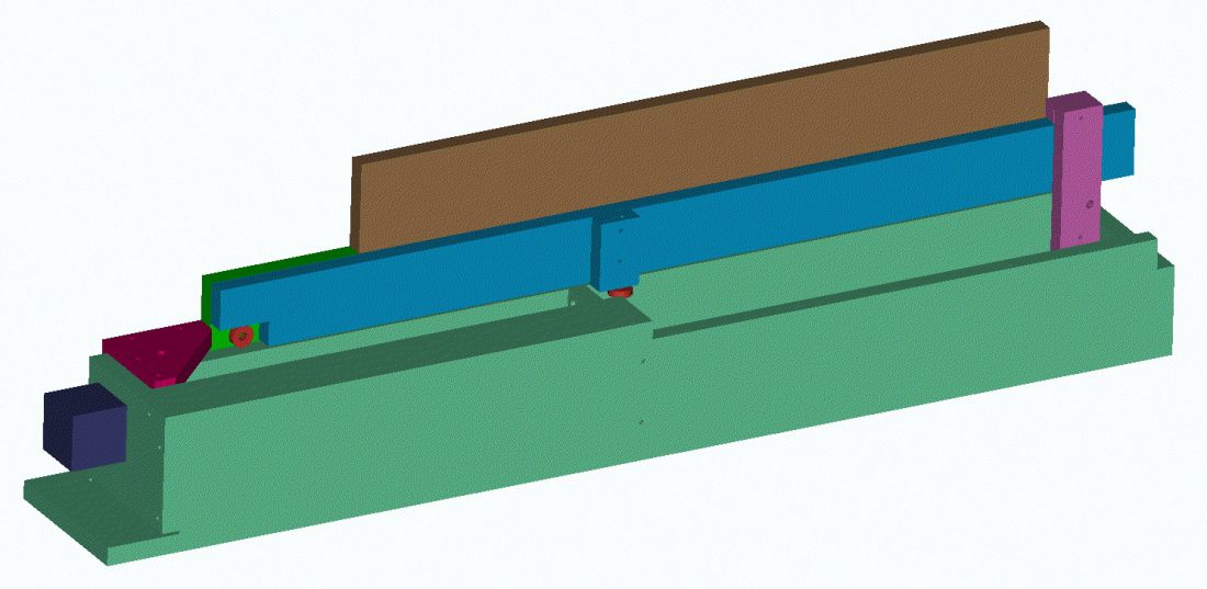
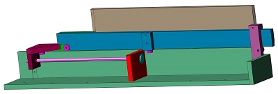
The figure below shows the sawing jig in startposition. The step motor is dark blue. The video above showed the front side. The picture below is looking from the back side (operator perspective).
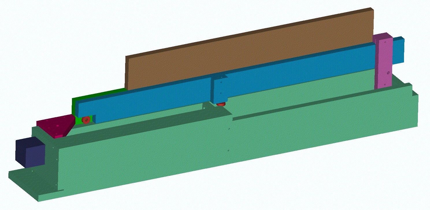 When the step motor spindle is halfway its range (full range is 430 mm), it looks like shown below (including the sacrificial materal in brown to prevent tear out):
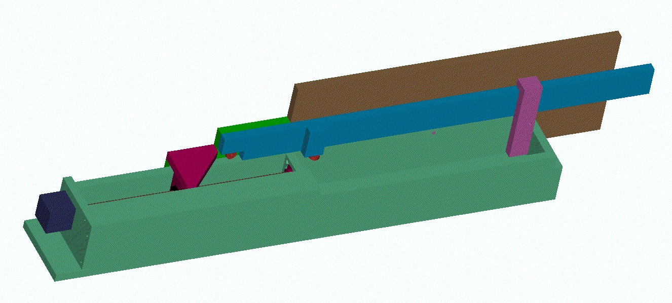
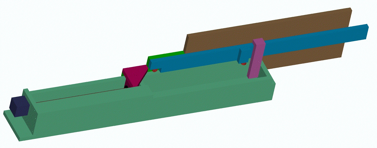
When the step motor spindle is at full range, it looks like shown below:
The Jointmaster box joint jig is optimized for minimum friction. The work-piece mass (+carriage mass) is carried by 2 bearings. One bearing is moving with the carriage, the other is standing still. The bearing moving with the carriage is the purple component attached to the green part in the pictures above. See picture below for the still standing bearing (in picture above the still standing bearing is hidden behind the purple box attachment, picture below is looking from the other side):
 To reduce friction with the side wall, there are two more bearings moving with the carriage. One of these side wall bearings is hidden below the part connecting to the spindle. Both side wall bearings are shown in the picture below (the front and top cover is removed to clearly see the step motor spindle): Please note that this bearing was not needed in the earlier video’s because we did not apply maximum workpiece mass yet. When we were finger jointing the zipper like finger joint table we modified the design as shown in this post.
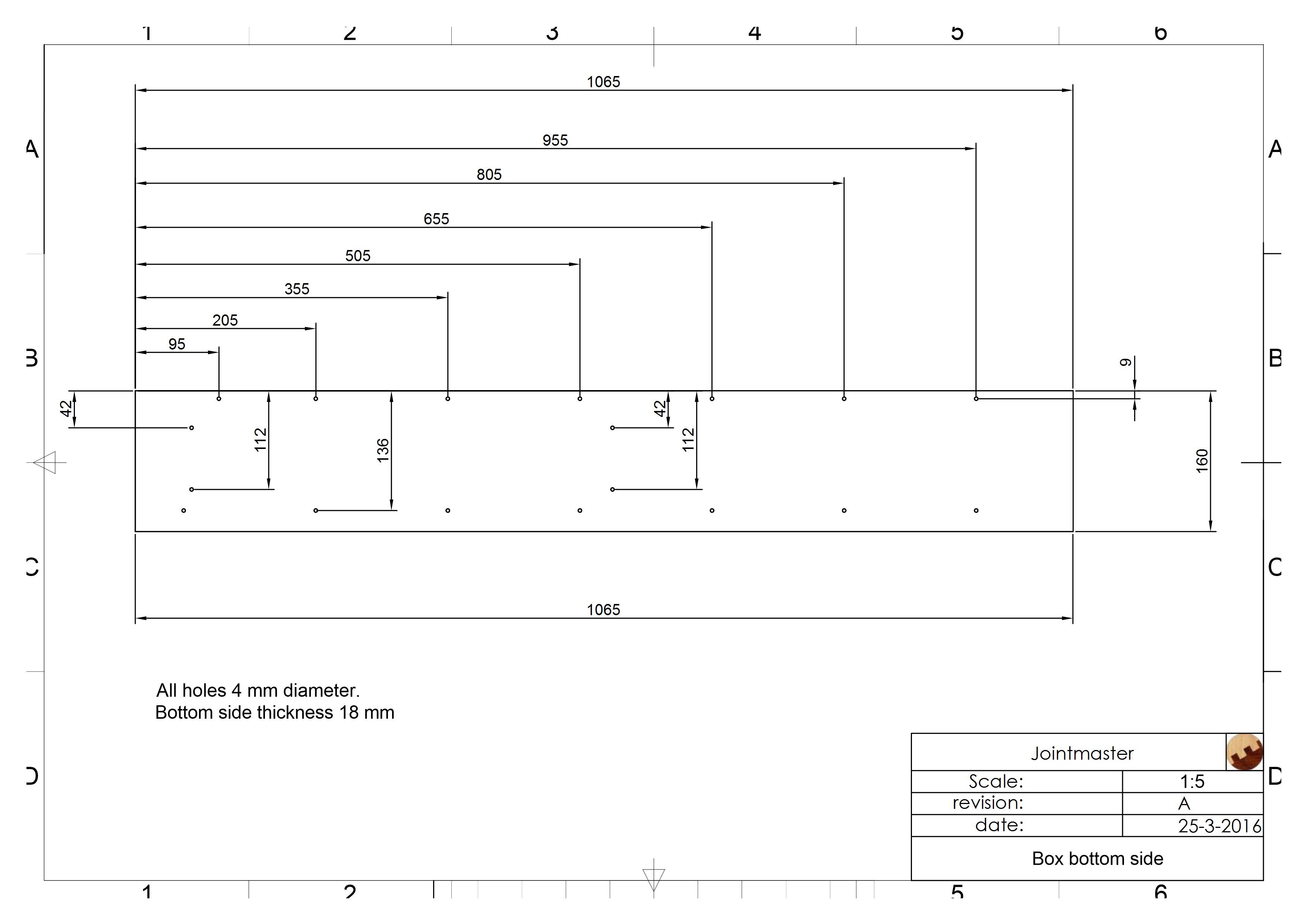
When you order the building plans in the shop, you can download all dimensions to create the Jointmaster box joint jig. You only need some drills, a screw driver and a saw to put the jig together. All material is 18 mm multiplex + wood screws.
For example the bottom side layout (dimensions in milli-meters) is shown below:
 You can also take a look at this Jointmaster video to understand how to put together the jig:
And here is an older (and refreshed) video that shows how to attach the circular guide, step motor driver + power supply for the Jointmaster Audio version.