Dear GOLEM,
When a milling machine is running for a couple of days, it might have processed around 1.000.000 Gcode constructs. These commands are communicated from the Linux CNC software to the Linux CNC controller. If either Linux CNC locks up, or the controller locks up or a stopswitch signals that boundaries are crossed while this is not the case, then your workpiece is ruined. If we allow only one in thousand workpieces to be ruined then the chance that the software fails due to any event should be at least 1 in 1.000.000.000. We say at least because the hardware can also fail. Like power supply, bearings, step motor overheats/ burns etc.
This is your required reliability. This is a very high number and you will have to be very careful to reach this number. The videos in this post show that EMI can completely destroy your reliability. In the past, we were working on a discontinued nonsense product called “Jointmaster PRO”. We had “Jointmaster PRO” running for a couple of days without problems(without running a step-motor in a test set-up). Doing the first test with a step motor, the control PCB reset without even running the step-motor (see part 1). If the EMI/ EMC problem is more subtle (for instance once every day) you will probably need more time to find the cause. Better do it right first time instead of building a dog-house enclosure…………
The video’s in this post show the discontinued product. The conclusions still hold and might help you. If grandpa has a pace-maker and you need some inheritance to get drunk, bring him near the chinese stepmotor driver that is in the video. Apps were starting automatically when holding the mobile phone near the step motor driver ! Inside the step motor driver is a resistor set-up like a powerful antenna dipole. Might be useful for radio broadcasting……
We discontinued the project because it did not conform to the KISS principle like Jointmaster does. Be simple and act simple !
Conclusions from this post:
- Use ferrite beads on all step motor driver inputs and outputs.
- Put step motor driver in a seperate compartment of the shielding enclosure. Do only trust the chinese driver we sell here in case you need inheritance from grandpa !!
- Put Linux CNC/ Jointmaster audio in a seperate compartment from the step motor driver and power supply.
- Use this grounding/ enclosure concept.
- Make sure your enclosure is well ventilated.
- Use Shielded cabling.
You have to comply to the following sub- requirements:
- The LINUX CNC computer should not be used heavily by other applications. (We did test with Internet on, starting applications etc, See part 3 of 2 in video’s below. This did not break communication but it will break at some point)
- The energy configuration should be such that the computer never goes into standby (screen may turn off)
- There should be no heavy EMI from the outside world
- Your computer memory should be high quality. Read this.
- Cabling should be shielded and grounding concept discussed below should be followed.
- PCB board should be shielded (discussed below)
- Cabling to step motor should be shielded.
- Enclosure around power supply and step motor driver should be shielded.
- The step motor driver has to be isolated by means of ferrite beads.
When testing the product for fingerjointing( thus only one step-motor is needed) we ran into a difficult EMI problem. The EMI problem was caused by an unshielded USB-cable which picked up the step motor driver radiated noise (25 MHz).
In part 1 (see video’s in this post) you can see how everything fits in the dog-house enclosure and we how we found the problem. In part 2 we investigate the problem. In part 3 the effect of ferrite bead and grounding is investigated. In Part 4 we solve the problem. From part 4 we draw the following reliability requirements:
- The step motor driver has to be contained in a seperate compartment without major cracks between outside world or power supply compartment.
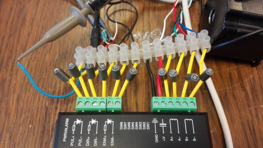
- The step motor driver inputs and outputs have to be filtered by means of ferrite beads (leading to 12 ferrite beads for every step motor driver). The enable, pulse and direction inputs are opto-couplers. Nevertheless, the 25 MHz signal is able to bridge this barrier as we did show in part 1 to 3.
- The step motor driver house has to be floating (i.e. not connected to ground or power supply minus)
- The power supply minus has to be floating(not connected to ground)
- The stop switch inputs/ outputs to the control PCB have to be filtered by means of ferrite beads.
- USB cables have to be shielded.
- Step motor power cable has to be shielded and shielding has to be connected to enclosure ground.
- Stop switch cables have to be shielded and connected to control pcb ground.
- Control PCB is floating inside control PCB enclosure. (Minus not connected to ground, otherwise ground loop will result)
And thus we can now answer the question if the doghouse enclosure is sufficient (See the video at the bottom of the page) ? No, the cracks to the outside world are too big and the step motor driver is not in a totally seperated compartment. Better to make the enclosure from video part 4 on this page.
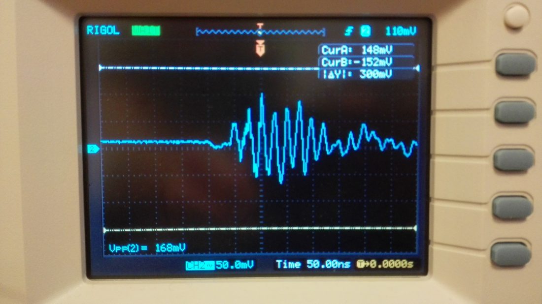
Note, as stated in part 4 we also measured the EMI problem in Jointmaster audio. 4 Volts peak to peak at 25 MHz !!!. It was very strange that so far we were able to cut finger joints without problems. Up to this moment we never held the Jointmaster stereo jack cable close to the step motor driver. If we do that without ferrite beads, the following happens:
– The Jointmaster app does sometimes not react or suddenly closes.
– Other apps suddenly start/ stop without touching the screen. Thus your phone (or your pacemaker) will show erratic behaviour !
Thus it is advisable that also the Jointmaster audio solution also has a descent enclosure as specified above. Note that we did a lot of tests not shown in the video:
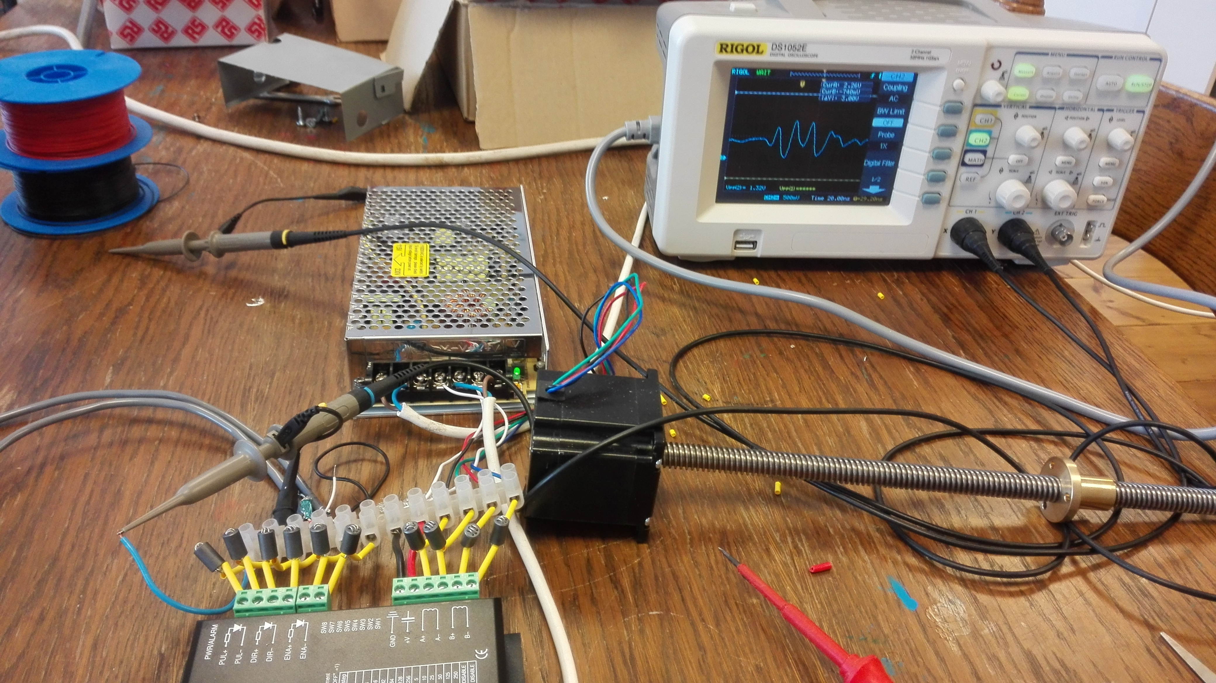
We added an extra set of opto-couplers between the step motor driver and the control PCB. Made no difference. We also did a test shown below where we removed the ferrite beads from the step motor driver minus and VCC. Immediately the 25 MHz peak to peak voltage went up to 1.32 Volts instead of 0.940 Volts. This proves that without ferrite beads on all inputs and outputs, the 25 MHz signal is spreading all over the place.
And of course a bonus. From crap to cradle. How to create your own dog-house enclosure (which provides insufficient reliability for g-code processing). The enclosure is the most expensive component. Because you need ventilation, you will always end up drilling a lot of holes if you buy a closed box enclosure. For this reason it is much cheaper and drill effective to simply use some old computer or video enclosure as shown below (And as said we are working on a version that has hardly any openings/ cracks):