
Dear Golem,
This post discusses the LINUX CNC grounding and EMC concept. You need a proper grounding EMC concept to have so called high reliability (The previous post on EMI and Reliability shows why we need this concept). Reliability shows how often a machine stops (does not fullfill its function). So lets say your car breaks down one time 100.000 driving hours. Then your car is extremely reliable.
The grounding and EMC/ EMI concept is shown below. We will discuss why we made these choices.
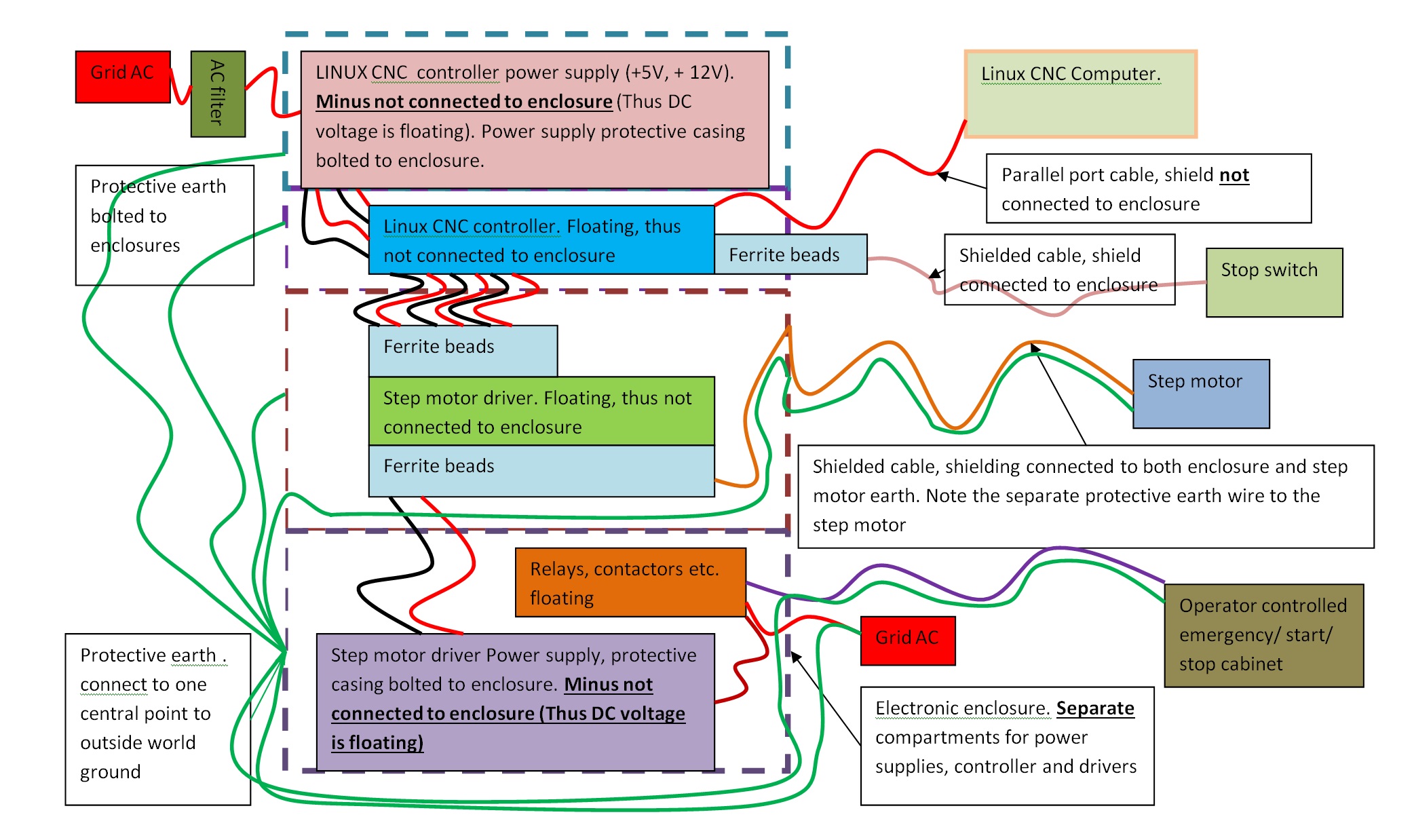
Electronic enclosure
The electronic enclosure is shown with a dotted line. It has the following main functions:
- protect operator from electric shock.
- protect Linux CNC operation from EMI/ EMC (both internal and external Electro Magnetic Interference)
- protect external appliances from EMC. (EMC radiated from power supply, step motor driver etc.)
- protect components from dust.
To protect the operator from electric shock, we need protective earth. The protective earth is connected to one point on the enclosure to prevent so-called ground loop effects. All radiated current eventually flows back to ground. The protective ground thus also has the function to lead back internally and externally radiated current (that could become EMC/ EMI problem) back to ground. You can decide for yourself if you need a clearly visible 16 mm^2 protective ground or if you integrate the protective ground in your other cabling.
Linux CNC controller
The Linux CNC controller has to be floating because every Windows computer minus is internally connected to ground. If we would ground the controller minus, every minus in the picture above becomes grounded and it becomes more difficult:
– to prevent ground loops
– to protect the operator from electric shock because you connect all internal components to ground and thus create an easy path for AC.
Note, if you decide to use an old computer power supply, then the computer supply minus is connected to ground. You run a higher risk on so-called ground loops. We did not test this so it might be that it works but could also lead to unreliability. If you decide to do this, make sure the Linux CNC computer and the Linux CNC controller power supply are feeding from the same AC grid point to prevent ground loops.
Linux CNC controller power supply
For high reliability (3 axis milling, long milling duration) it is better to have a seperate power supply for the Linux CNC controller. The step-motor drivers and power relays are very noisy as proven in the EMI and Reliability post. The power supply has to be in a seperate compartment from the controller. The power supply also needs an AC filter to prevent influence from the outside world from messing up reliability (heavy motors starting, welding machines).
Step motors
The step-motors need shielded cables to prevent EMI from outside world to enter the system. Shielding is also needed to prevent the high frequency content in the cables from leaving the system. The step motor also has to be connected to ground to:
– lead radiated EMC inside the step-motor housing to ground.
– prevent build-up of static electricity(sparks in a dusty environment can be hazardous).
The step motor cable shielding has to be connected both at the enclosure and at the step motor side 360 degrees circumferential. Do not use so called pigtails. Google on “pigtail”, “clips circumferential EMC and you know why. You can also use these connectors. If you ever have to move your equipment for shows or other events, you will really appreciate connectors. Note that you can decide to run the protective earth wire inside the shielded cable or use a seperate wire to the motors (might be required in ATEX environment). Of course you can also decide to use shielding as protective earth. Read the post on safety and health to learn more on the risks involved.
Instead of connectors you can also use 360 degrees circumferential (homemade) sheet metal clips
Stop Switches
The stopswitches need shielded cables to prevent EMI from outside world to enter the system (for example large motors/ welding machines starting in your neighbourbood). The stop switches shielding has to be connected both at the enclosure side 360 degrees circumferential. Do not use so called pigtails but use these connectors.
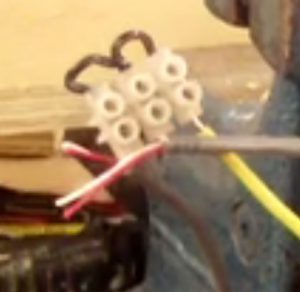
The picture below shows 2 shielded cables that have been pigtailed to a grounded wire. It does not look so nice and does not give EMI/ EMC protection.
The stop switches are connected to the Linux CNC controller using ferrite beads. We discovered that upon enabling the stepmotors inside Linux CNC, we immediately got a stopswitch error. The stopswitch wires act as antennas for every EMP signal. The start-up pulse was visible in the Linux CNC on board scope. Thus we added ferrite beads. This was sufficient to damp the signal. For this reason, run stopswitch wires as far away as possible from (step motor) power wires.
Step motor driver power supply
We will run a seperate post how you can build a cheap heavy DC power supply yourself (70 Volts, 10 A). In this way we disconnect all men in the middle + we enable you to maintain the power supply yourself. Of course the power supply is powered from an AC filter for reliability (Prevent EMC from outside world entering the system). AC filter is part of the etc. in the relay box.
Step motor drivers
To keep the noise inside all step motor drivers need ferrite beads on all inputs and outputs. This was discussed in the post on EMI and reliability. The step motor driver house has to be floating. We measured that the EMI problems where worse when the step motor driver house was grounded. Only one step motor driver is shown above. In reality there is a step motor driver for every axis of course.
Fans for cooling
Because you stack all heat generation equipment in a cabinet you need cooling and cooling holes. We use 2 fans. One pulling air from below near the step motor driver power supply and one above pushing out air in the step motor driver compartment.
Operator control cabinet
The operator controls power to the Step motor power supply, relays and mill. There is a emergency button on the control cabinet that powers everything down in case of emergency. Never trust the software for this task. Automatic starting of the mill is not provided in our software for safety reasons. We will run a seperate post on the control cabinet.
The operator first has to power the relay box with 2 switch buttons before he can switch the mill on and off. See video below why this is needed.
Relay/ contactor box
Because we switch DC high Amperage, we have big sparks leading to welded permanent relay connections. Because of high amperage with big capacitors there is high chance of your workplace circuit breakers exceeding their maximum. Thus this totally ruins your machine reliability. We will run a seperate post on this subject.